Because I am tired of messing around with the SD cards, and I want to make time-lapse videos.
Motivation
I learned about OctoPrint a few years ago, but at that time it was said that time to time the raspberry pi to run it would crash and it’s not really increasing the printer reliability, but rather, hindering it. Nowadays things have changed, hopefully.
Whatever, take me to the TR:DL already
Basic setup
So first we install Raspbian lite on some old SD card and do the basic configuration of the RPI. Connected to a monitor I complete the most basic setup before continuing over SSH and starting the project related configurations.
- set a new password
- set the host name
- set the WIFI country and settings
- on the interfaces, enable the camera and the SSH
Also check what’s this machines MAC address ip address and configure my router to assign some IP address to it. Run apt upgrade while we are at it. After setting up the router and finishing the updates run sudo dhclient -r to release the current IP address lease. We should now obtain the new fixed address from the router. If not, try and sudo dhclient.
Now we should be able to SSH to pi without further problems.
Enable USB boot
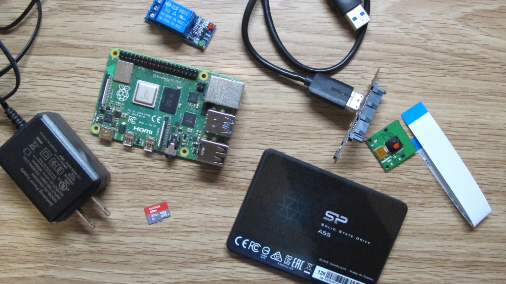
Since I would like to take time-lapse videos of my prints, I choose to use an external USB SSD instead of the SD card. This has multiple advantages, most importantly it’s a lot faster and I likely won’t run into troubles of a worn out and failing SD card. In the middle of a print. Which wouldn’t only suck for the print, but also, I have to repeat this entire setup. I rather spend the extra 20 bucks on the external drive and save that time in the future. Probably even a USB thumb drive is a better choice than the SD card, but don’t quote me on that.
For my setup, I will use one of the cheapest SSDs currently on the market and one of the USB-to-SATA chips I have left over from the external HDDs that I used for my home server.
First of all, install byobu (and git), before anything goes wrong with the SSH session.
sudo apt install byobu git and continue the session in byobu
Now we connect the external drive. This took longer than expected, in the kernel message output I can see the drive first identifies as the 5TB drive it used to be and some error messages, but in the end it shows up as what it really is under lsblk. Note that it is listed as “sda”
pi@octo:~$ lsblk
NAME        MAJ:MIN RM   SIZE RO TYPE MOUNTPOINT
sda           8:0    0 119.2G  0 disk
mmcblk0     179:0    0   3.7G  0 disk
├─mmcblk0p1 179:1    0   256M  0 part /boot
└─mmcblk0p2 179:2    0   3.4G  0 part /
Next, we clone and install rpi-clone. Some script that was written for this use case, move and expand the SD card to an external drive.
git clone https://github.com/billw2/rpi-clone.git
cd rpi-clone
sudo cp rpi-clone rpi-clone-setup /usr/local/sbin
Than just run the progress, the github page is a bit confusing, but I think the first option is what I want, so it is what I used. This is what happened.
pi@octo:~$ sudo rpi-clone sda
Error: /dev/sda: unrecognised disk label

Booted disk: mmcblk0 4.0GB                 Destination disk: sda 128.0GB
---------------------------------------------------------------------------
Part      Size    FS     Label           Part   Size  FS  Label
1 /boot   256.0M  fat32  --
2 root      3.4G  ext4   rootfs
---------------------------------------------------------------------------
== Initialize: IMAGE partition table - partition number mismatch: 2 -> 0 ==
1 /boot               (242.0M used)  : MKFS  SYNC to sda1
2 root                (1.3G used)    : RESIZE  MKFS  SYNC to sda2
---------------------------------------------------------------------------
Run setup script       : no.
Verbose mode           : no.
-----------------------:
** WARNING **          : All destination disk sda data will be overwritten!
-----------------------:

Initialize and clone to the destination disk sda?  (yes/no): yes
Optional destination ext type file system label (16 chars max): rootfs

Initializing
  Imaging past partition 1 start.
  => dd if=/dev/mmcblk0 of=/dev/sda bs=1M count=8 ...
  Resizing destination disk last partition ...
    Resize success.
  Changing destination Disk ID ...Re-reading the partition table failed.: Device or resource busy

  => mkfs -t vfat -F 32  /dev/sda1 ...
  => mkfs -t ext4 -L rootfs /dev/sda2 ...

Syncing file systems (can take a long time)
Syncing mounted partitions:
  Mounting /dev/sda2 on /mnt/clone
  => rsync // /mnt/clone with-root-excludes ...
  Mounting /dev/sda1 on /mnt/clone/boot
  => rsync /boot/ /mnt/clone/boot  ...

Editing /mnt/clone/boot/cmdline.txt PARTUUID to use d8b7caf6
Editing /mnt/clone/etc/fstab PARTUUID to use d8b7caf6
===============================
Done with clone to /dev/sda
   Start - 13:00:49    End - 13:03:49    Elapsed Time - 3:00

Cloned partitions are mounted on /mnt/clone for inspection or customizing.

Hit Enter when ready to unmount the /dev/sda partitions ...
  unmounting /mnt/clone/boot
  unmounting /mnt/clone
===============================
Running lsblk again we can see the partition table exists now, running raspi-conifg I wanted to enable USB boot if the SD card fails. But this is not possible without updating the RPI boot eeprom. This happens automatically every reboot, the state can be checked running sudo rpi-eeprom-update or sudo rpi-eeprom-update -a. There is more information about it on the official page.
After rebooting it was fixed and calling raspi-config -> Advanced Options -> Boot Options -> USB Boot was a success. And shutting down, removing the SD card and rebooting worked like a charm.
pi@octo:~ $ lsblk
NAME   MAJ:MIN RM   SIZE RO TYPE MOUNTPOINT
sda      8:0    0 119.2G  0 disk
├─sda1   8:1    0   256M  0 part /boot
└─sda2   8:2    0   119G  0 part /
Installing OctoPrint
Install python, buildtools and virtualenv. Than set it up. All according to this guide.
cd ~
sudo apt install python3-pip python3-dev python3-setuptools python3-venv git libyaml-dev build-essential -y
mkdir OctoPrint && cd OctoPrint
python3 -m venv venv
source venv/bin/activate
pip install pip --upgrade
pip install octoprint
sudo usermod -a -G tty pi
sudo usermod -a -G dialout pi
Since we had to add the default user to the dialout group to access the serial interface to talk to the printer, we need to log out and back in to make this change take effect in the current session. Before starting any of it, we set up the webcam and haproxy now, too.
Haproxy’s install is pretty straight forward, just install it and download the config from here.
sudo apt install haproxy
curl -O https://www.himitsu.dev/var/20/setting-up-the-3d-printer-with-octoprint/haproxy.cfg
sudo mv /etc/haproxy/haproxy.cfg /etc/haproxy/haproxy.cfg.back
sudo mv ./haproxy.cfg /etc/haproxy/
Installing the raspi camera and mjpg streamer
First install a bunch of stuff again
cd ~
sudo apt install subversion libjpeg62-turbo-dev imagemagick ffmpeg libv4l-dev cmake -y
git clone https://github.com/jacksonliam/mjpg-streamer.git
cd mjpg-streamer/mjpg-streamer-experimental
export LD_LIBRARY_PATH=.
make
Next install some scripts to control mjpg streamer as a deamon and autostart it.
cd ~
mkdir scripts
cd scripts
curl -O https://www.himitsu.dev/var/20/setting-up-the-3d-printer-with-octoprint/webcam
curl -O https://www.himitsu.dev/var/20/setting-up-the-3d-printer-with-octoprint/webcamDaemon
chmod +x ./*
Next, we shutdown the RPI, install the camera module and than try to run those scripts and test if we can actually see an image
/home/pi/scripts/webcam start
If that is the case, we add this line to /etc/rc.local. In my case this didn’t really work, because apparently my camera was broken.
If you can get a picture with raspistill --nopreview -w 640 -h 480 -q 5 -o ./pic.jpg than it should be fine. I only got an error that I should check the cameras sunny connector. It didn’t help.
Starting and configuring OctoPrint
Now it’s time to take care of the main program. First of all, we add a service file to automatically start at system startup
wget https://github.com/OctoPrint/OctoPrint/raw/master/scripts/octoprint.service
sudo mv octoprint.service /etc/systemd/system/octoprint.service
sudo systemctl enable octoprint.service
After starting the service for the first time, and visiting the service on port 5000, there is a wizard for the setup. This is pretty strait forward as there are a lot of explanations on what the settings actually do. At one point, we have the option to define a few server commands, let’s do it.
- Restart OctoPrint:
sudo service octoprint restart - Restart system:
sudo shutdown -r now - Shutdown system:
sudo shutdown -h now
Likewise, at the webcam setup step, we can put in the following values, since we already set up the mjpg stream server. Important to note is, the stream URL needs to be reachable by the remote machine. OctoPrint will just embed the link to stream on it’s UI, but not resolve it. I added the printer servers fixed ip to my hosts file, so I can access it using a name.
- Stream URL:
http://octo.home/webcam/?action=stream - Snapshot URL:
http://127.0.0.1:8080/?action=snapshot - Path to FFMPEG:
/usr/bin/ffmpeg
After this, I only removed the octoprint watermarking from the timelapse in the settings.
Adding a relay for PSU control
Now to turning on or off the printer without moving away from the PC, I followed this guide. Basically, just cut the printer power cord and add a relay. There is a plugin for OctoPrint already that enables switching the relay. Take care where to connect the relay and setup the plugin accordingly, that’s it.
As far as the plugin goes, it’s called PSU Control. install it from the plugin manager and restart. This results in a small lightning icon, where we can toggle the PSU.
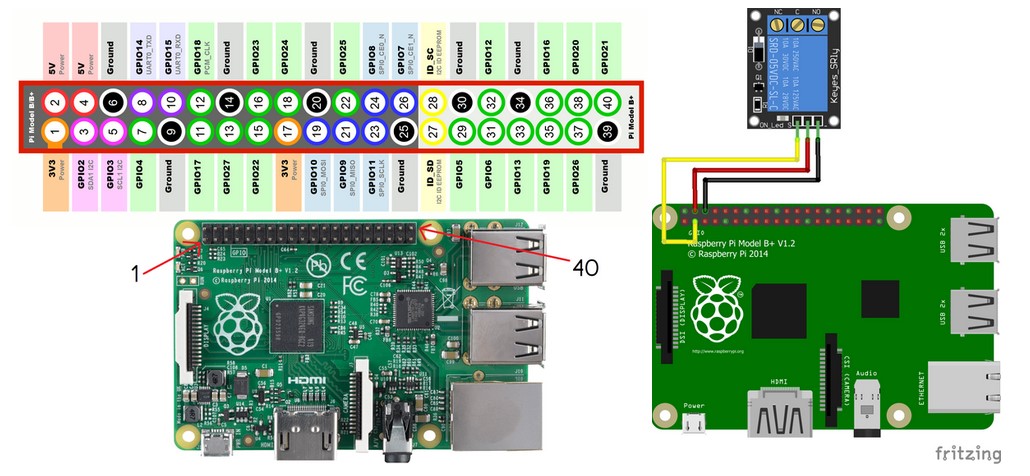
According to the guy who made the guide and the picture of the pins:
" If you used the pins 3,4 and 6 on your pi as I suggested then for the On/Off GPIO Pin enter 3. If you used any other pins then here you’ll select which pin is being used as the signal for the relay. Do NOT enter the number after the GPIO but the number of the pin. For example, if you’re using GPIO21 you’ll enter 40 because GPIO21 is on pin 40. "
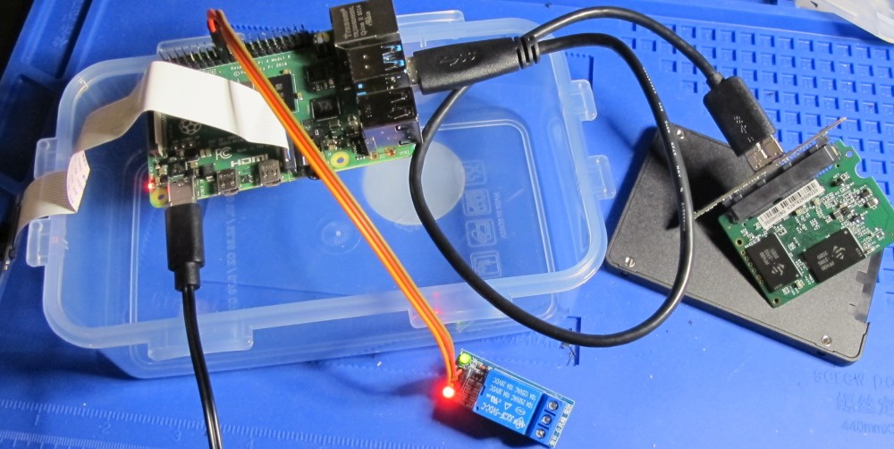
In my case, the 5V relay didn’t switch when paired with one of the 3.3V pins as control. I could fix this by using a 3.3V VCC instead, even thou on the relay it looks like there is a transistor to act as a voltage converter. Anyway, time to cut some cables and… well test it first
Putting it all together
For the case of this setup I choose some Tupperware, sturdy, cheap, easy to modify. I removed the case of the SSD and printed some stands for the pi, so I can safely sandwich them. Drilled a few holes, made a power split between the pi’s PSU and the printer, now all that is missing is proper mounting, the camera holder and maybe some more ventilation holes. But for now, I will run like this until I printed the camera holder
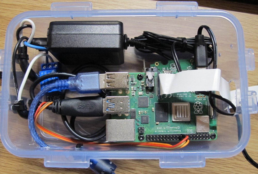
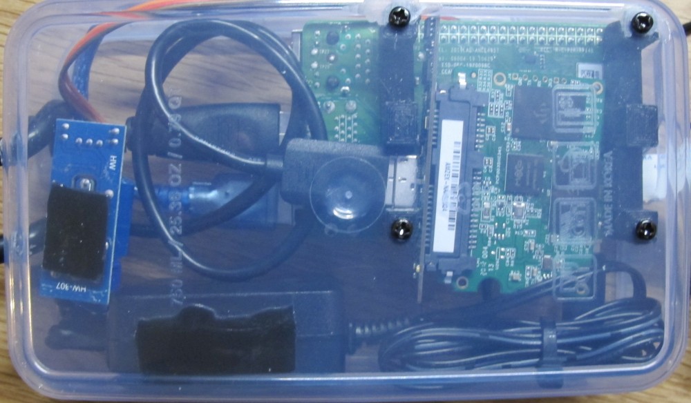
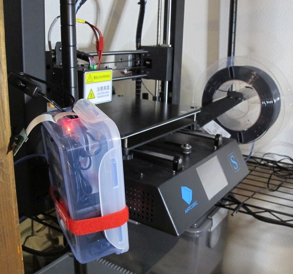
Beautiful
TL;DR
Maybe there won’t be a TLDR for this post.